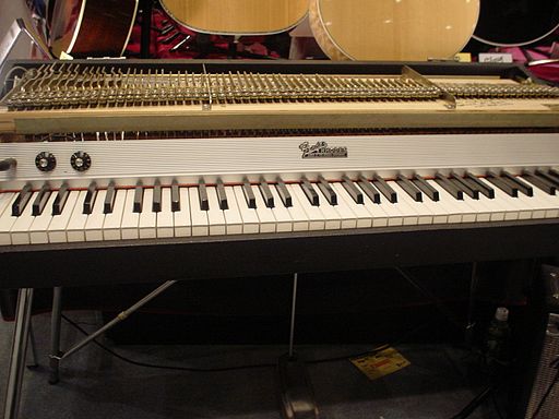
Simulation of the Fender Rhodes
This is a companion page for the article Passive simulation of the nonlinear port-Hamiltonian modeling of a Rhodes Piano submitted to the Journal of Sound and Vibration.
Parts under consideration
Operating principle

Full schematic
The complete system is quite complex (38 components mentioned for each note in figure below). The resonator is an asymmetric tuning fork (elements 7 to 13 and 19 in the figure), where one of the prong is call the tine (element 13) and is struck by the hammer (elements 14 and 15), the other prong is called the tone bar (element 11). The constant magnetic induction field due to the pickup magnet in free air is modulated by the movement of the (magnetically conducting) tine, which results in a change of the magnetic flux in the coil, that generates an electromotive force (voltage) from Faraday's law of induction.

Retained part
This paper focuses on the part depicted in the figure below, from the hammer (excited by a force) to the pickup (producing an output voltage).

Proposed modeling
In the paper, this part is simplified and modeled by three multi-physical elements (see figure below):
- a nonlinear hysteretic hammer \(\mathcal{H}\), with adjustable material characteristics and geometry,
- a linear damped cantilever beam \(\mathcal{B}\), which can be tuned according to the shape and material properties,
- a nonlinear pickup \(\mathcal{P}\), the transverse and longitudinal position of which can be adjusted compared to the free-end beam extremity, which is connected to a RC analog filter (not represented in the figure below).
The technical details about the modeling of each part and the construction of the complete model are given in the paper.

Simulation code
The resulting simulation code (Python 2.7) is available here (the script to be executed is 'MAIN.py'). All the results presented in the paper and in the sequel of this web page were obtained from this code. Notice the tuning of physical parameters may differ from the parameters specified in the paper, which correspond to the case note A440, with contant damping coefficient.
Comparison with measurements
Here we compare the simulated output (labeled simulation) to measurements provided by UVI (labeled measure) for note A4 (440Hz) with increasing force applied to the hammer.


Audio examples
Below we give some audio results obtained from the aforementioned modeling and numerical simulation. Each example is made of successive hammer hits with increasing force amplitude. Results are given for A1 (55Hz), A2 (110Hz), A3 (220Hz) and A4 (440Hz).
- 55Hz
- 110Hz
- 220Hz
- 440Hz
Positioning the pickup
Below are audio examples that show the effects of the positioning of the tine with respect to the pickup.

Increasing the distance between the pickup and the beam.

- \(l_p=0.5mm\)
- (Too close)
- \(l_p=1.5mm\)
- (Ideal)
- \(l_p=3mm\)
- (Low volume)

Displacing the pickup from the beam's axis.

- \(l_\delta=0mm\)
- (Pure overtone)
- \(l_\delta=0.5mm\)
- (Ideal)
- \(l_\delta=1.5mm\)
- (Pure Tone)

