| LISTEN HRTF DATABASE | CONTEXT | SYSTEM & PROTOCOL | DOWNLOAD | TOOLS |
| DEMO SOUNDS | LINKS | GLOSSARY | BIBLIOGRAPHY |
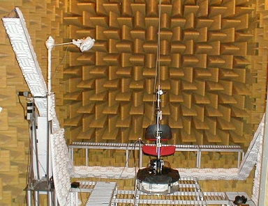
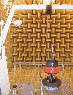
The HRIR measurement campaign was performed in our anechoïc room (8.1 × 6.2 × 6.45 = 324 m3); the room is covered with 1.1m long glass wool wedges absorbing sound waves above 75 Hz. Measurement equipment lay on a configurable metallic duckboard.

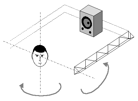
Loudspeaker is moved by a crane, an U-shaped metallic structure covered with melanine panels. Elevation of the crane is performed by a couple of step-by-step motors, driven by a dedicated power unit controlled by the computer. Elevation angle is chosen by the measurement software, and a feedback is sent by an angular sensor.
 |
 |
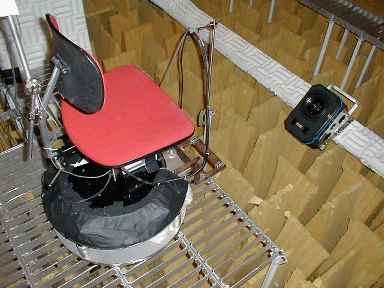
The subject to be measured is sitting on a rotating chair. The system consists of a B&K 9640 turntable, two iron plates, and a common office chair. The chair is fixed to the upper iron plate, and the upper iron plate is fixed to the slip ring of the turntable. The turntable is connected to a B&K 5960 controller by serial link, and the controller is driven by an IEEE-488 interface.
 |
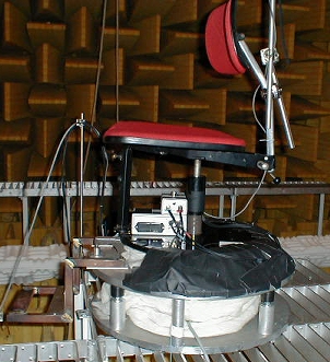 |
The chair is adjustable in height and has a steel bar for footrest. An aluminum mount was attached in the chair's back rest, with headrest, helping subjects to keep the head straight ahead; its position is adjustable in height and tilt. Azimuth angle is chosen by the measurement software, and feedback is sent by an optical sensor.
Validation of head position is performed by a head tracking system linked to the measurement software; receiver is held on head's top of the test subject. This allows triggering the measurement signal only when subject's head is at the correct position, and saving the actual position of the measurement.
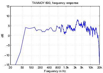
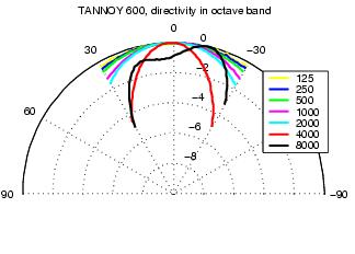
We use a TANNOY system 600, which represents a good compromise between sound quality and weight. The loudspeaker was driven by a YAMAHA amplifier.
Subject's torso and head, which have the main influence on the HRTF data, are viewed by the loudspeaker under a 7 degrees angle; thus we measure the loudspeaker response corresponding to directions around the system axis.
For measuring the impulse response of the loudspeaker, we use a B&K omnidirectional microphone type 4149 (0.5 inch) with B&K 2801 amplifier; the test signal used is a logarithmic sweep. Position of the microphone capsule is as near as possible as head center of the subject. You can download this impulse response.
 |
 |
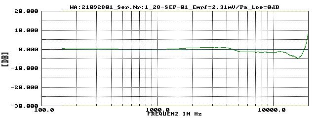
We use a pair of Knowles FG3329 miniature microphones having a very small size (diameter 2.54 mm, height 2.54 mm), relative low price, and excellent quality. An custom preamplifier was designed, with 40 dB gain.
For measuring the impulse response of the microphone, we use a B&K artificial mouth; the test signal is Schröder noise. Position of the microphone is 50 cm far from the source.
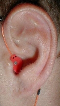 |
We perform HRIR measurements in blocked-meatus conditions. The front side of the capsule was at the entrance of the ear canal, and as the meatus is occluded, it prevents resonance of the ear canal. Capsule was inserted in a subject-customized silicon putty, which ensure the capsule is kept firmly in place and the microphone could be placed in the same position later. Blocked meatus is the most suitable measurement position for acquiring HRTF [Hammershoi96, Riederer98]. |
The procedure is controlled by an Apple Macintosh G4 500 MHz with 256 Mb RAM, running MacOS 9.2, and a RME Multiface soundcard (36 channels 24 bits/96 kHz I/O box).
The measurement software is a real-time library for Max/MSP.
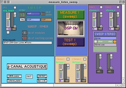
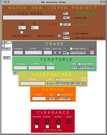
This is a full real-time application which allows measuring impulse responses with sweep signals and synchronously deconvolving the microphone signal; this allows a quick visualization of the impulse response. Moreover, the application controls all the devices.
We use a 8192 points logarithmic sweep as measurement signal (44100 Hz), and two channels inputs (one for left ear and another for right ear).
Instead of noise, measurements with sweep are considerably less vulnerable to distortion and time variance. Using a sweep somewhat longer than the room impulse response to be measured allows the exclusion of all harmonic distortion products, practically leaving only the background noise as the limitation for the achievable signal-to-noise ratio. The sweep can thus be fed to the loudspeaker with considerably more power without introducing artifacts in the acquired impulse response [Farina00, Müller01].
The following table shows HRIR measurement points :
| Elevation (degrees) | Azimuth increment (degrees) | Points per elevation |
| -45 | 15 | 24 |
| -30 | 15 | 24 |
| -15 | 15 | 24 |
| 0 | 15 | 24 |
| 15 | 15 | 24 |
| 30 | 15 | 24 |
| 45 | 15 | 24 |
| 60 | 30 | 12 |
| 75 | 60 | 6 |
| 90 | 360 | 1 |
The setup consits of 10 elevation angles starting at -45° ending at +90° in 15° steps vertical resolution. The steps per rotation varies from 24 to only 1 (90° elevation). Measurement points are always located at the 15° grid, but with increasing elevation only every second or fourth measurement point is taken into account. As a whole, there are 187 measurement points, hence 187 stereo audio files.