First of all it must be noted that there are two different meanings of
the word interpolation. One meaning refers to finding a value of a
function that is given only at discrete points, when the value is
inbetween two of the given points. With spectral envelopes, we use interpolation in this
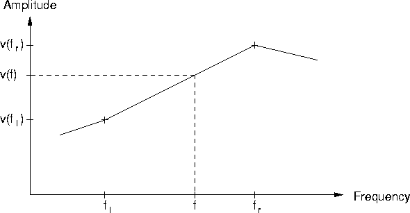
sense when we want to know the value of the envelope v(f) at an
arbitrary frequency f, which is not one of the given points of the
envelope.
6.1
If fl and fr are the two points closest to f, then the
linear interpolation is:
The second meaning of interpolation is finding an intermediate state
in the gradual transition from one parameter set to another, in our
case going from one spectral envelope to another. This interpolation between
envelopes is in fact a weighted sum of the spectral envelopes. It can
always be reduced to the first sense of interpolation, in that we take
the linearly interpolated values v1(f) and v2(f) for each
frequency f of two spectral envelopes and interpolate between them by an
interpolation factor m. If m=0 we will keep the original
spectral envelope v1, if m=1 we will receive the target spectral envelope v2:
When dealing with the spectral envelope of speech or the singing voice, we want to respect the formant structure of the envelope. This means that if we want to interpolate between two spectral envelopes, we don't want the amplitudes at each frequency interpolated as in equation (5.2), but shift the formants from their place in the original spectral envelope to that in the target spectral envelope. In fact, we want to simulate the effect of interpolating the articulatory parameters of the vocal tract. Figure 5.4 explains the different approaches.
The prerequisites for shifting formants in this way are of course that we know where the formants are located, and which formant in the original spectral envelope is associated with which formant in the target spectral envelope. The former is not at all obvious and is a question of formant detection . The latter is even more difficult for an automated method without providing manual input. It is a question of labeling the formants of successive time frames to generate formant tracks.
Fortunately, for some applications, we know a priori where the formants should be. For example, when treating the voice in a piece where the lyrics are known, like an opera. Then it is known which vowels are sung, and thus we can look up the formant positions in the formant tables from phonetics literature. In this case, the spectral envelope representation would be augmented by fuzzy formants, or a spectral envelope representation using exact formants will be provided, as described in section 4.5.
The fuzzy formant representation of spectral envelope consists of an envelope in spectral representation plus several formant regions with an index for identification. Given two spectral envelopes with two fuzzy formants with the same index, it is still not clear how the intermediate spectral envelopes, with the formant on its way from its position in the original envelope to that in the target envelope, are to be generated. Several questions arise: How to fill the hole the formant leaves when it starts to move away? What to do with the envelope in the places the formant moves over? How should the shape of the formant change between the original and the target shapes?
After an idea by Miller Puckette, it is possible to interpolate an envelope in spectral representation in a way that formants are shifted exactly as we want. The idea is to first integrate over the envelopes (in the discrete case, this amounts to building the cumulative sum of the spectral envelope), and then to horizontally interpolate between the integrals. We retrieve the interpolated formant by subsequent differentiation of the result.
 |
That the idea works can be seen in figure 5.5. Formally,
the method can be described like this:
Starting from two spectral envelopes v1(f) and v2(f), considered as
continuous functions over
![]() ,
we construct the
cumulative integral functions V1(F) and V2(F), and normalize:
,
we construct the
cumulative integral functions V1(F) and V2(F), and normalize:


 :
:

Unfortunately, this works only for one formant to be interpolated, as can be seen in figure 5.6. Nevertheless, we can do better if we have the information of formant regions, i.e. we know where the two formants to be interpolated lie in their respective spectral envelopes. In this case, we can restrict the technique of horizontal interpolation of the integral to the given formant regions, with an appropriate fade-in and fade-out of the region borders.
 |
If both of the two spectral envelopes to be interpolated are given as precise formants with their index i, center frequency fi, amplitude ai, and bandwidth bi as parameters, interpolation becomes trivial. Simply the formant parameters need to be linearly interpolated, using equation (5.1) accordingly.
Summing up the different possibilities of interpolation of spectral envelopes, we can recognize a hierarchy in the spectral envelope representations in regard of formant interpolation. The hierarchy is, from highest to lowest:
With each step down we lose some information necessary for formant interpolation. We can convert downwards step by step:
We cannot, however, convert upwards, because that would mean adding information (by simple calculations, that is--of course, methods to detect formant shapes in spectral envelopes exist, but these are the subject of a field of research of its own.)
This means that, when spectral envelopes in different representations have to be interpolated, we can't do better than going down to that representation of the two which is lowest in level, discarding the formant information of the higher one.