From Section 2 we see that an input wave
![]() is delayed by a time-varying input-delay
is delayed by a time-varying input-delay
![]() during its nonlinear propagation. The output wave
during its nonlinear propagation. The output wave
![]() is observed
is observed ![]() after it enters the
waveguide:
after it enters the
waveguide: ![]() . Using now a signal processing
description, we express the output s at time t as a function of
the present and past of the input e, which leads to
. Using now a signal processing
description, we express the output s at time t as a function of
the present and past of the input e, which leads to
![]() , where
, where ![]() is the output-delay.
is the output-delay.
In the linear approximation, the speed c is constant, so that the
physical and signal processing points of view become identical and
![]() .
But when the speed c varies in time, no trivial relationship remains
between
.
But when the speed c varies in time, no trivial relationship remains
between ![]() and
and ![]() . Since the waveguide is to be modelled by a
fractional delay filter, we have to design an efficient system for
converting the input delay
. Since the waveguide is to be modelled by a
fractional delay filter, we have to design an efficient system for
converting the input delay ![]() into the output delay
into the output delay ![]() , which
controls the filter delay.
, which
controls the filter delay.
Let us define two time scales ![]() and
and ![]() , as:
, as:
![]()
These two time-scales being defined, we may recast the two primary relations describing the propagation as:
![]()
Under the constraint that ![]() or
or ![]() is
reversible
is
reversible![]() , we deduce that the two time-scales
are mutually reciprocals:
, we deduce that the two time-scales
are mutually reciprocals:
By introducing the definitions of ![]() or
or
![]() in Eq. 6, we obtain the final relations:
in Eq. 6, we obtain the final relations:
![]()
which may be recast as implicit equations using traditional notation:
Provided that ![]() or
or ![]() are inverse functions, their curves
are symmetrical about the
are inverse functions, their curves
are symmetrical about the ![]() axis, which also represents
the identity time-scale (Fig. 2). In this graphical
representation,
axis, which also represents
the identity time-scale (Fig. 2). In this graphical
representation, ![]() at time
at time ![]() measures the vertical distance
between the axis of symmetry and curve
measures the vertical distance
between the axis of symmetry and curve ![]() , whereas
, whereas ![]() measures the vertical distance between the axis and curve
measures the vertical distance between the axis and curve ![]() ,
which is also the horizontal distance between the axis and the curve
,
which is also the horizontal distance between the axis and the curve
![]() .
.
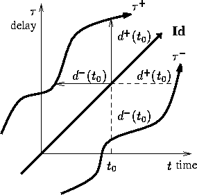
Figure 2: Graphical interpretation
The graphical representation clearly proves that the ![]() to
to ![]() conversion is causal, since the horizontal line measuring
conversion is causal, since the horizontal line measuring ![]() intersects the
intersects the ![]() curve on its left, corresponding to
the past of the signal. In other words, knowing the past of
curve on its left, corresponding to
the past of the signal. In other words, knowing the past of
![]() is sufficient to determine
is sufficient to determine ![]() .
.
The input-output generic relation ![]() is to be
interpreted as the linear filtering of the input e(t) by a
delay filter of delay
is to be
interpreted as the linear filtering of the input e(t) by a
delay filter of delay ![]() , but we get Eq. 8 by
formally substituting e by
, but we get Eq. 8 by
formally substituting e by ![]() and s by
and s by ![]() in this generic
input-output relation. This is to be interpreted as a filtering
relation between
in this generic
input-output relation. This is to be interpreted as a filtering
relation between ![]() and
and ![]() (see Fig. 3). Thus
the
(see Fig. 3). Thus
the ![]() to
to ![]() convertion must be understood as a delay filter
whose delay is controlled by its output. The feedback loop is the
origin of the nonlinearity of the system.
convertion must be understood as a delay filter
whose delay is controlled by its output. The feedback loop is the
origin of the nonlinearity of the system.
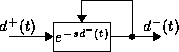
Figure 3: Formal interpretation
In Eq. 3 we note that the input-delay depends on the
amplitude of the input wave. Provided that there exists an instantaneous
one-to-one relation g between the input wave and the input-delay,
![]() , we show in Eq. 9 that the output
wave is deduced from
, we show in Eq. 9 that the output
wave is deduced from ![]() by applying the inverse relation
by applying the inverse relation ![]() :
:
Therefore a complete continuous-time nonlinear one-way propagation model of the waveguide includes first a system mapping the input wave into a delay, then a delay filter controlled by feedback converting input-delay into output-delay, and finally a third system mapping back the delay into the output wave.